


n2585722
-
Posts
161 -
Joined
-
Last visited
-
Days Won
43
Content Type
Profiles
Forums
Store
Gallery
Events
Local Fish Stores
FAQ
Blogs
Downloads
Everything posted by n2585722
-
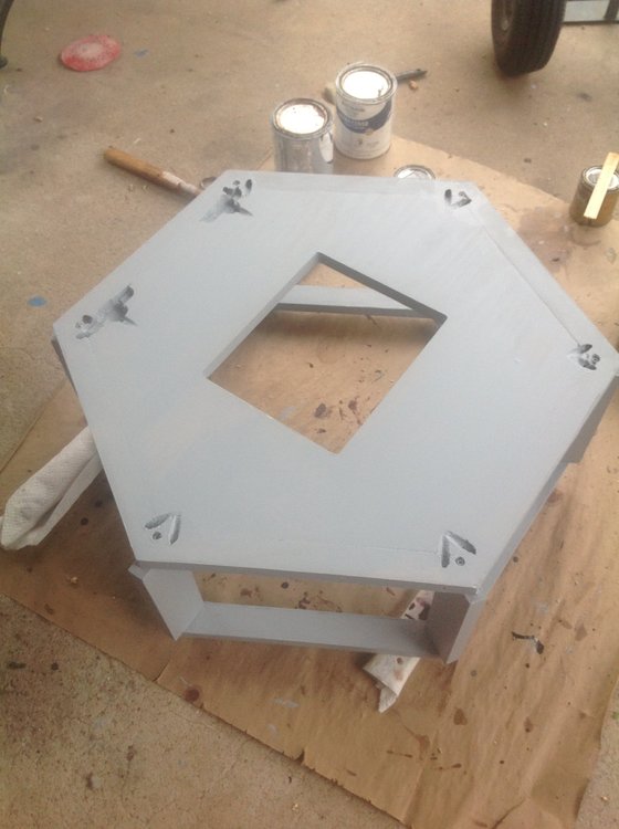
Stand Continued The photo below is the inner frame assembly painted. The area painted black is the electronics area and the bottom of the frame assembly. The rest is painted white with a rubber coating added. The photo below is a view from above. It show the trim around the top. This will hopefully keep any small water spills in the inner frame assembly and hopefully off the floor. Below is a photo from the rear. The holes in the front panel are visiable here. The cutout for the pass through has a cut above it. This is for installing a flap to keep any water splashes out of the electronics area. Below is a view from the side. The two side post are trimmed on both sides. this can be seen on the far post in this view. The inner frame assembly or the actual stand was filled with water to check for leaks. I was able to get around three gallons into the bottom. With the sump in place it will reduce this amount quite a bit. After a few hours I determined there were no leaks and proceeded with the rest of the build. This assembly alone will support the weight of the tank without any issues when it is filled with water.


-
Stand Continued On to the bottom of the inner frame. The photo below shows the six pieces for the bottom. There is a cut all the way around the bottom. This matches the cut on the inner side of the lower inner frame. Once in place the top of the bottom will be the same height as the top of the lower inner frame. Below is the bottom view of the bottom assembled. Below is the top view of the assembled bottom. Below is a photo of the bottom in place in the lower inner frame. In the photo below are the parts to the front panel. This is where the modules will be mounted for the controller. There are inserts set at the proper position to mount the modules. I will get to the controller later on. Below is a photo of the assembled front panel. Below is a bottom view of the inner frame assembled and glued. The pocket holes have been plugged. Below is a view of the assembled inner frame front view. This shows the front side of the front panel. There is a cutout that will be the pass through for all the cables from the sump area. It is higher than the lower braces. This is in case the bottom fills with water it will overflow over the braces before entering the electronics area. The inserts for mounting the side panels can be seen on the post in this view. This a view from the top. The two cuts in each top section is to drain any spill back inside the inner frame assembly. There will be some trim glued around the top outer edge of the sections. The photo below shows the sump in place. Also the holes in top of the front panel are for conduit that will run from the front panel to the back cabinet. Below is a view from the top with the sump in place.


-
Stand Now on to the stand. The stand consist of an inner frame which is the actual stand for the tank. Top outer frame and lower outer frame along with the side panels. The back panel has a cabinet attached to it for the power and some of the electornics. Below is photos of most of the wood used for the stand. All three photos are of the same parts just different angles. As you can tell there is little more here than on the canopy. The wood for the back cover is also in these photos. In the photo below the darker pieces of wood bottom center left are the post for the inner frame. I will start with the lower inner frame. The sections were made out of 2x4's that were trimmed down with a planer.Below is a photo of the sections ready to be assembled. There are several cuts using a router. The inner cuts are for the stand bottom. The cuts on the ends are for the vertical post of the stand. The post are tapered toward the inside of the stand. This was done to allow a wider sump to be used inside the stand. The sump will fit into the stand two different ways. That required that two of the post were tapered on both sides. The other four post were tapered on one side only. The non tapered sides face either the front or back of the stand. Most of the weight load will be on the wide area of the post anyway. Below is a photo of the top of the lower inner frame assembled. The sections for the upper inner frame are show in the photo below. The sections for the lower inner frame are stacked to the right in this photo. The upper inner sections have the same end cuts as the lowere inner frame section. The only real difference is there is no cut for the bottom. Below is a view from the top of the assembled upper inner frame. This is where the tank will eventually sit. The pocket holes will be plugged once the assembly is glued together. Below is a view of the bottom of the upper inner frame. Below is a photo of the post attached to the lower inner frame. Along with the taper in the back of the post they also are trimmed down to 3/4" centered. This was done with a table saw and required four cuts to acheive. The cuts from the side were done at an angle to allow them to fit flush with the back of the side panel. If you look close you can see the inserts that are used with screws to attach the side panels. There are four inserts in each post. The photo below has the upper inner frame attached. The stacks beside the assembeled frame are the braces that go between the post just below the upper inner frame and just above the lower inner frame. Notice the one edge with the 15 degree cut. These will angle down toward the inside of the stand. Hopefully this will minimize water leakage to the flooring and keep in inside the stand. In the photo below the bracing has been attached between the post. The front does not have the lower bracing. It will have a back panel for electronics this will be enough bracing. The upper brace is there since it is used as extra support for the weight of the tank. I will get to the bottom and the front panel later.


-
So far I have not had an issue, but I have a large heat sink and two fans to cool the heat sink. Sent from my XT1056 using Tapatalk
-
Thanks Sent from my iPad using Tapatalk
-
Canopy Continued I finally got around to adding the inner door panels to the canopy doors and the hinge covers to the side panels. It took 3 years though. I guess that is what I get for filling it up with water before I finished. The stand already has these installed. To do this I had to remove each side panel one at a time. To get the side panels off I had to remove the upper outer frame assy. Below is a photo with the lid up on the canopy. I left the lights running while doing this. I will get into the lighting later on. As you can see it is a little dusty. I don't usually have to open the lid. Below is a photo with the lid removed. This makes it easier to get access to the back screws holding the top frame assembly to the inner frame. Below is a photo of the top frame removed from the canopy. There is a little dust but other than that it all looks good. Below is a photo of some of the new assemblies at various steps. The two blocks in the upper left is two hinge covers before any cuts were made with the router. It shows the top and bottom. Next to them is a acrylic template used for the first router cut. Below it is a wooden template. Just to the left of it is a cover with the first router cut made. The two to the left of that are a couple with all cuts made. On the upper right is the three parts that make up the door panel. Bottom left is a door panel glued and sanded. to the right of that is one that has been glued but not sanded. Below is a panel that has been removed from the canopy. I replaced the hinges at this time also. Below is a photo of all the parts along with the side panel. Below are two photos of the side panel with the inner door panel installed and the hinge covers installed. It is ready to install back on the canopy. Below is the canopy with the panel removed. This happens to be the front panel that is off in the photo. The photo also reveals how the side of the panels mate with the inner frame assembly. The photo below is with one of the completed side panels back on with the door open. The next three photos are after the panels were all completed and canopy was back together. That is about it for the canopy for now. The covers will hopefully protect the doors and the hinge covers will help make the door hinges last a little longer. Also it helps divert some of the air flow to the stand with the help of the panels. It will not completly cut off the air flow through the canopy since I still want some air flow through there.


-
Canopy Continued Now to the stain and paint. On the exterior I used Minwax Bombay Mahogany. I wiped it on and off to get the color I was after. I did 2 aplications and then added a two coats satin polyurethane over this. For the electronics compartment I used a flat black. For the area exposed to water I used a gloss white covered with a rubber coating. Below is a photo of the bottom of the top outer frame assy and lid assembly ready for install. The holes through the black blocks in the corners are how this assembly is mounted to the canopy inner frame assy. Below is a top view of the top outer frame and lid assy. The photo below is the canopy placed on the tank with the doors closed. I have a piece of tape attached to open the lid at this point. Below is a photo with the doors open. If you look closely at the lower inner frame section you can see the 15 degree angle.


-
Canopy Continued I guess now is the time to show some photos of the canopy assembled. In most of these photos it was assembled for testing purposes. The photo below was after it was reassembled and parts glued, but before staining. Doors were not installed here. In this photo you can see where the lid and inner outer frame have been beveled to match where they come together. The photo below is a view with the lid open. This photo was after it was reassembled and parts glued together. Also the pocket holes have been plugged. Doors were not installed here. The photo below is a view from the back showing the back panel. You can also see the bottom of the inner frame also. This is what sits on top of the tank. The side panels and lower outer frame hang below the top of the tank. The photo below is a view through the door of a side panel. Below is a photo from the top with lid open. The photo below has the acrylic barrier in place. The photo below has the LED assembly in place. Below is the upper rail of the side panels with exception of the back panel. It has a pattern cut on the top to allow ventilation of the top compartment. You can also see the 15 degree cut at the bottom of the rail that was discussed earlier. The photo below shows the vents at the top of the side panels and the corner column that is formed buy the two sides of the side panels. This has the insert in place. I purchase these from Home depot I beleive with the pattern already embossed. I just cut it to the correct lengths.


-
Canopy Continued Below is a photo of the parts to a side panel and door assy. The door is a raised panel door that consist of 5 parts. Upper rail, lower rails, left stile, right stile and door panel. Door panel is upper center. Stiles are upper right with the rails in between. The side panel consist of left half column, left stile, upper rail, lower rail, right stile and right half column. These parts are the same on the stand with the exception of the length of the half columns, stiles and door panel. The photo below is of the left half column and left stile with the rails to the right. The half column is cut for the addition of a insert in the front to hide the junction of two panels. It is also cut to mate with the vertical rails on the inner frame of the canopy. The stile is cut at an angle on the side that mates with the half column. The upper rail has the lower edge cut at a 15 degree angle going down toward the inside of the panel. The lower rail has the same 15 degree cut also dropping toward the back of the panel. I did this to hopefully keep water spills to the outside of the tank to a minimum. The inner frame also has sections added that also have this 15 degree slant down toward the center of the inner frame on both the top and bottm. Below is photo of an assembled panel from front with door attached and open. This was assembled for testing and the door does not have the final cuts around the outside. Below is a view of the side panel from the back with door attached. The back panel is different as there is no door and no lower rail. This allows for the overflow box to be mounted to the back of the tank. Below is a photo of the back panel assembled.


-
Making Outer Frame Sections This is a good spot to talk about making the outer frame sections. After the sections are cut I used templates to get the pattern cut into the section. I also made a frame out of some scrap wood to get the templates placed correctly on the section. Below is a photo of the templates the frame and a section. The outer sections are used for both the canopy and stand so there were 24 used. The templates were made using several pieces of wood taped to the mdf to guide the router bit. I used some scrap pieces of mdf to make the templates. The photo below shows the section placed into the frame ready for the templates to be installed. If you notice the section is recessed compared to the frame. This is to help place the templates correctly. The next photo shows the templates ready for install. The next photo shows one of the templates installed. Then next photo shows both templates installed. The next photo is the section removed from the frame with the templates installed. The section is ready for the cutout to be done. Once it is done the templates are removed. In the photo below is the router bit used to make the cuts. Since the cut does not go all the way through the wood I used a bit with the guide bearing at the bottom. This was also done on a router table and not a hand held router.


-
Canopy Continued Below is a photo of a lower outer frame section with the inner side trimmed. Below is a photo of the bottom view of the upper outer frame assembled. Notice the cutout pattern for the top of all the side panels and back panel. Below is the top view of the upper outer frame assembled. Also you can see the cutout that matches that on the lid so the lid will sit flush. The top of the inner frame inside has a bevel along with the top of the lid. This will be noticed better in the photos of full assembly. Below is the top view of the lower outer frame . Also notice the cutout for the bottom of all the side panels and back panel. Below is the bottom view of the lower outer frame. The pocket holes will be plugged on final assembly. Also there will be two holes drilled to mount the frame to the bottom of each side panel. Side panels are held in place by these bottom screws to the lower outer frame and the top screws to the inner frame.


-
Canopy Continued Below are photos of parts for the upper outer frame, Lower outer frame and lid. Directly below is the upper outer frame parts including bracket for lid hinges. Below is the lower outer frame parts. Below is the parts for the lid. The cutout for the fans was done the same way as the cutout on the inner barrier. To the right you can see the holes for the hinges. Also the outer edges are trimmed all the way around to match the trim inner side of the top outer frame which is trimmed. This is a bottom view of the parts. Below is a section for top outer frame. The ones for the lower outer frame is the same with inside trimed off. The stand uses the same outer frame sections also the only difference is how much of the inner side is trimmed off. Also there is a pattern cut out of the section that matches the top or bottom of the side panels.


-
Thanks, I did make my share of mistakes along the way. This it the first major project like this for me. The next one is new cabinets for my wife. Then to the stand and canopy for the 110 using what I learn from this build. It did take me almost seven years to get it to the point I could fill it and start using it.
-
Canopy Continued Below are photos of the seperate inner frame parts assembled. Directly below is the upper inner frame assembled. Below is the lower inner frame assembled. Below is the barrier assembled top view. The cutouts for the hinge are visable at the top of the barrier. Below is the bottom view of the barrier. The pocket hole plugs have not been installed in this photo. The hole was cut using a 3/8" router bit with a bearing at the top using a template. Below is the template used for this. I attached it using the doubled sided foam tape. Drilled a hole larger than the router bit and used the router bit to cut out the hole. This was done on a router table and not a hand held router.


-
Canopy Continued Below is photos of the parts for the inner frame assembly. The first photo is the parts to the barrier between the electronics compartment in the top of the canopy and the area above the tank. The hole for the acrylic was cut out using a router and template with the barrier assembled. This is a photo of dissassemble parts after the hole was cut. Once it was glued the pocket holes were plugged. Below is the parts for the upper inner frame. The back part has some cutouts so the hinge for the top lid clears the frame. The barrier also has these cutouts. This was assembled with wooden dowels and glue only. The cutout on the inner side of all the parts match a cutout on the parts of the barrier. Below is lower inner frame parts with the vertical post. The lower inner frame was also assembled with dowels and glue only. The veritcal post between them were attached with screws.


-
Canopy I figured I would start with the canopy Since that was where I started the build. below is a photo of the peices required for the canopy cut and ready for assembly. This photo was acctually taken after dissassembly from testing. it is ready for staining and reassembly. The wood is pine like what you can get at a local Lowes or Home Depot. The canopy consist of an inner frame and a upper outer frame with lid, a lower outer frame, 5 side panels and a back panel. Photos of the inner frame assembled with primer are below. This sits on top of the tank. The bottom inner frame has no link in the back. This is because this tank is not drilled for a sump and I decided to use a overflow instead of attempting to drill holes in the glass tank. The pocket holes in each corner are there to attach the side panels at the top. The rectangular hole in the top is for an acrylic barrer between the area above the tank and the LED assembly. The electronics in this build will be seperated fron the areas that are exposed to potential water splashes or water vapor. I am hoping that this will prevent premature failure of my electronic components. So far after 3 years I have had no failures on any of the components in the separated compartements


-
Thanks, I have got it started now. Danny Sent from my iPad using Tapatalk
-
Back in 2008 I decided I wanted to get back into the hobby. I wanted to try using LED's for lighting. At that time there were just a few commercially built units available. I decided to do a DIY LED system as an experiment. I had a 42 gallon hex tank that was not in use. I decided to use it. I figured it would be cheaper to use it than the 110 I have. To do this I decided to build a canopy to house the LED fixture. My wife had some requirements if I set the tank back up. She did not want to see any equipment hanging off the back of the tank. She did not want to see the water line or top of the tank. Also she did not want to see the sand or gravel against the side of the tank at the bottom. The photo below is what I came up with. I will go into the details of building this in future post. Since I am local I decided to add a build thread for this on this forum. The photo below is a recent photo of the tank. It has been up and running for about 3 years now.

-
Thanks, I will give it a try.
-
I hoped that there was a way other than using another site as a host.
-
How do you post photos in a build thread?
-
✋ I plan on going.
-
I apologize for just chiming in on this but here goes. Well water is notorious for depleting DI resin. One cause is CO2 in the water. Your TDS is also very high to begin with. I suggest you talk to an expert about what it will take to get more life out of you resin. You might ask at thfilterguys.biz, buckeyefieldsupply.com or spectra pure. I think all of them have a forum on reefcentral where you can ask. Not all situations require the same methods. Danny


